

You've got a physical part. No drawings. No original CAD file. Maybe it's a discontinued component, a legacy casting, or a custom piece someone machined decades ago.
The old way is slow, expensive, and painful. The new way? Scan it, process it, and walk away with a production-ready CAD file in hours.
Here's what you need to know
The basics
What is reverse engineering with 3D scanning?
In manufacturing, reverse engineering is the process of extracting design intent from a physical object and converting it into an editable digital model. When no original CAD exists, or it's been lost, corrupted, or never created, reverse engineering is how you rebuild it.
A professional scanner reads a part's surface and outputs a point cloud: millions of measured coordinates that map the object's exact shape. That point cloud becomes a polygon mesh (STL, OBJ, or PLY), and scan-to-CAD software like QUICKSURFACE reconstructs the mesh into solid CAD geometry (prismatic features, freeform surfaces, parametric bodies) that manufacturing teams can use downstream.
According to QUICKSURFACE's documentation, the software supports recreating missing CAD data, modifying existing parts, and preparing scanned components for engineering and manufacturing. QUICKSURFACE 2026 is built on the Siemens Parasolid engine, adding reliability and interoperability for teams feeding scan-to-CAD output into larger engineering pipelines.
The core scan-to-CAD workflow
Every stage matters, and the quality of your tools at each stage decides whether you end up with a clean CAD file or a rebuild that takes longer than manual measurement. New to the capture side? Start with 3D Wonders' deep dive into 3D scanning technology.
Why it matters
Why scan-to-CAD workflows matter in modern manufacturing
Legacy part reconstruction
When a supplier disappears or a drawing gets lost, scan-to-CAD is often the only viable path: capture the existing part, reconstruct the geometry, and produce a CAD-ready model without guesswork.
Faster product development
Scan an existing part, modify the CAD model, and send updated geometry to a CNC machine or 3D printer within the same day, compressing design-to-production cycles.
Manufacturing continuity
Tooling wears, fixtures get damaged, and custom jigs rarely come with CAD. Digitizing critical production hardware before it degrades creates a reliable baseline for replacements.
Digital twin creation
As-built digital twins need real-world geometry, not just design intent. Scan data feeds simulation, quality inspection, and predictive maintenance because it reflects what the part actually looks like.
Product improvement and redesign
You can't improve what you can't measure. A precise digital baseline lets teams identify inefficiencies, optimize surfaces, and iterate without starting from scratch.
Engineering teams often struggle to manually rebuild organic shapes, compound curves, and legacy castings that were never designed parametrically. QUICKSURFACE accelerates this directly from scan data, without forcing users back into traditional CAD rebuilds. Compare options in the 3D Wonders reverse engineering software range.
How it works
How 3D scanning reverse engineering works
1. Capturing geometry with 3D scanners
Professional reverse engineering scanners are either structured light or laser line scanners. Both project patterns or lines onto a surface and use cameras to calculate depth from how they deform across the geometry. The 3D Wonders technology guide covers the differences in detail. The EinScan Rigil Series uses a hybrid system of 25+25 crossed blue laser lines, 7 parallel laser lines, and infrared VCSEL to capture high-resolution data across a wide range of materials and lighting conditions.
A stricter accuracy standard: according to SHINING 3D's official Rigil Series page, each device is tested against a 1000 mm sphere rod five times before shipping, and the maximum deviation (not the average) is reported as the accuracy spec.
Scan resolution
Higher resolution captures finer detail but generates larger files.
Accuracy spec
How closely captured data matches real geometry, in mm or microns.
Surface finish
Glossy or reflective surfaces may need scanning spray.
Part size
Large parts often require multiple setups.
2. Converting point clouds into meshes
Raw point clouds are dense and unprocessed. Turning them into usable mesh geometry requires aligning multiple scan passes (registration), filtering outlier noise, and generating a continuous polygon surface. Gaps, noise, or non-manifold geometry here compound through the rest of the workflow.
Universally supported; common for manufacturing and 3D printing
Supports texture data; common in design and visualization
Common in research workflows; supports point cloud attributes
3. Transforming meshes into CAD
The mesh describes shape. Converting it into editable CAD requires surface reconstruction: extracting the design intent and rebuilding it as manufacturable geometry. QUICKSURFACE combines parametric feature extraction (planes, cylinders, cones, and other prismatic shapes) with freeform NURBS surface fitting for organic geometry.
Hybrid modeling, mixing both types in a single model, is what makes real-world parts reconstructable.
Step by step
The complete scan-to-CAD workflow, step by step
Scan the physical part
Position the part for complete coverage. Complex geometry needs multiple setups to capture all faces without occlusion; use reference markers or geometric targets to assist alignment across setups.
Create a mesh
Import aligned scan data and process it into a polygon mesh: clean noise, fill small holes, and optimize density, reducing polygon count in flat areas while preserving resolution at edges and complex geometry.
Import into QUICKSURFACE
QUICKSURFACE accepts the cleaned mesh and provides native scan alignment tools to register geometry references, inspect mesh quality, and set up reconstruction regions.
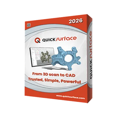
Scan-to-CAD software
QUICKSURFACE
A 64-bit application handling up to 100 million triangles, so even high-density industrial scans don't need external decimation. Built around scan-to-CAD, unlike general-purpose CAD tools that treat mesh data as an afterthought.
Explore QUICKSURFACE →Reconstruct CAD surfaces
The core reverse engineering work: fit planes, cylinders, and other analytic surfaces to prismatic regions, then build freeform NURBS surfaces over organic geometry. An automotive bracket might combine machined bosses (parametric) with cast organic fillets (freeform), and QUICKSURFACE handles both in one session.
Deviation analysis compares the reconstructed CAD against the original mesh throughout the process. Color-mapped heat maps show where the reconstruction matches tightly and where adjustments are needed.
Export CAD files
Completed models export to manufacturing-ready formats:
Teams combining EinScan Rigil hardware with QUICKSURFACE consistently shorten scan-to-CAD cycles, with less friction at every handoff from calibrated scan to finished reconstruction.
Why QUICKSURFACE
What makes QUICKSURFACE different from traditional CAD tools?
Most CAD platforms weren't designed for scan data. Mesh import exists, but reverse engineering requires scan alignment, mesh-referenced surface fitting, deviation analysis, and hybrid modeling in a single environment, which traditional parametric modelers don't natively provide.
In 2025, QUICKSURFACE was named “Best 3D Scan-to-CAD Solution 2025” by SME News and received the “Most Innovative Use of Reverse Engineering Techniques in Manufacturing Solution” award from Manufacturing Today (source).
Rebuilding a complex part in SolidWorks from a mesh reference can take days. In QUICKSURFACE, it typically takes a fraction of that time.
Already in SolidWorks? QUICKSURFACE for SolidWorks (Mesh2Surface) runs as a native add-in: no platform switching, no file format juggling, and a deviation analyzer that works on any SolidWorks body at near-instant speed.
The hardware
EinScan Rigil Series overview

Industrial reverse engineering
EinScan Rigil Series
From $3,499.00
A professional tri-mode laser 3D scanner designed for industrial reverse engineering, quality inspection, and dimensional analysis. It runs standalone (no PC), wireless via Wi-Fi 6, or wired, giving teams flexibility across part sizes and workflows.
High-resolution scanning
The Rigil delivers volumetric accuracy up to 0.04 + 0.06 mm/m and geometric resolution down to 0.05 mm (SHINING 3D Rigil Series specs). For context, 0.04 mm is about half the width of a human hair, the level engineering-grade work on machined components, castings, and precision automotive parts needs.
Worst-case, not best-case: SHINING 3D's CNAS-accredited lab tests every Rigil five times with a 1000 mm sphere rod before shipment and reports the maximum deviation, so the spec-sheet accuracy is a floor, not a best-case result.
Tri-mode operation
Standalone
Fully self-contained, no PC needed; ideal for field or shop floor work where cables are impractical.
Wireless PC
Connects via Wi-Fi 6 to leverage desktop computing for complex projects and large datasets.
Wired PC
Maximum throughput and stability for high-volume or demanding sessions.
Material compatibility
Blue laser and infrared VCSEL handle dark plastics, painted metals, and most carbon composites without scanning spray. Highly polished metals or transparent materials may still benefit from spray. The 5MP color camera captures texture for photorealistic output.
Large and small part scanning
25+25 crossed lines enable fast wide-area scanning, while 7 parallel lines switch in for fine detail, merging both datasets in a single project file, so you don't need separate hardware for large assemblies and small precision parts.
Explore the full EinScan Rigil Series, including the Rigil Lite option, on the 3D Wonders EinScan Rigil product page.
Real-world example
Reverse engineering a Volkswagen van spindle
Here's what this actually looks like in practice.
The original problem
A Volkswagen van spindle, a complex, safety-critical steering component, needed reproducing. No CAD, no drawings. Compound curves, precision bearing seats, and organic cast transitions would've taken days to reconstruct from caliper measurements.
Capturing geometry with EinScan
Scanned in multiple setups to capture machined bearing interfaces, cast arm transitions, and threaded sections, with reference markers maintaining registration. Result: a clean, complete point cloud in one coordinate system.
Importing into QUICKSURFACE
The registered point cloud was processed into a mesh and imported, with mesh quality validated for holes, noise, and non-manifold regions before reconstruction.
Building the CAD model
Prismatic features (bearing seats, bolt faces, shafts) became parametric features with precise dimensional control; the cast arm body and organic transitions were fitted with NURBS surfaces, combined into one model preserving design intent.
Deviation analysis
Built-in deviation analysis compared the finished CAD against the scan mesh, confirming the reconstruction matched within tolerance across all critical surfaces.
Export to SolidWorks and Fusion 360
Exported as STEP, ready for manufacturing drawings, FEA analysis, or CNC programming.
What this achieved
A complex, safety-critical automotive part went from physical object to production-ready CAD in a single workflow session, without a single manual measurement.
Benefits
Benefits of modern reverse engineering workflows
Faster project turnaround
Parts that required days of caliper work, sketching, and modeling from scratch are captured in hours and reconstructed within the same day.
Improved CAD accuracy
Optical scanning captures geometry directly from the surface, removing the measurement uncertainty, transcription mistakes, and missed features of manual work.
Reduced human error
Fewer manual steps, fewer failure points. Deviation analysis gives a numeric answer to "how close is this reconstruction?" instead of visual judgment.
Manufacturing-ready output
QUICKSURFACE produces STEP and IGES files directly usable in CAM, FEA, and drawing workflows: an engineering-grade CAD model, not a visual representation.
Easier design iteration
Once a part exists as editable CAD, geometry can be modified, analyzed, and sent back to production without re-scanning.
For where scan-to-CAD fits into evolving manufacturing technology, including AI-assisted workflows and cloud processing, see 3D Wonders' overview of 3D scanning industry trends.
Troubleshooting
Common reverse engineering challenges and how to solve them
Reflective surface issues
Metals, polished plastics, and chrome scatter laser light. A temporary scanning spray creates a matte coating that removes cleanly afterward. 3D Wonders carries scanning sprays and accessories for EinScan and FreeScan systems.
Incomplete scan data
Occluded surfaces create mesh holes. Repositioning and adding setups covers most regions; internal channels and bores may require CT scanning.
Poor mesh quality
Artifacts, noise, and non-manifold geometry cause downstream reconstruction problems. Fix them at the mesh stage; it's faster than discovering errors during surface fitting.
Compare
QUICKSURFACE vs other reverse engineering software
QUICKSURFACE
Engineering teams that need a capable, scan-native RE environment without Geomagic's enterprise price or the limits of mesh-only tools. Hybrid modeling covers precision machined parts to organic castings in one workflow.
View QUICKSURFACE →Geomagic Design X
When part complexity is extreme, parametric reconstruction depth is the priority, and budget isn't the main constraint.
View Geomagic Design X →Mesh2Surface
SolidWorks-centric teams that want RE tools inside their existing environment, mainly for moderately complex geometry. SOLIDWORKS lists it as a certified partner add-in.
View Mesh2Surface →Fusion 360 mesh tools
Light-duty mesh referencing and simple surface extraction, not production-grade RE of complex parts.
3D Wonders also carries other professional-grade reverse engineering software for teams where QUICKSURFACE isn't the right fit.
Buyer checklist
Choosing the right 3D scanner for reverse engineering
The EinScan Rigil Series targets industrial reverse engineering, where accuracy, surface compatibility, and workflow flexibility matter more than entry-level pricing. Its all-in-one design (built-in computing, display, storage, and wireless) removes the usual trade-off between portability and processing power. Browse the full professional 3D scanner collection to compare accuracy tiers and working volumes.
Industries
Industries using 3D scan-to-CAD workflows
Manufacturing
CNC manufacturers reverse engineer worn or legacy tooling, validate as-manufactured geometry, and reconstruct undocumented fixtures, supporting quality control and production continuity.
Automotive restoration and customization
Discontinued body panels, custom suspension components, and one-off fabricated parts can be scanned, reconstructed, and reproduced as direct replacements or improved versions.
Aerospace engineering
MRO operations reconstruct legacy structural components, create baselines for wear tracking, and validate repaired geometry. Tight tolerances make scanner accuracy critical.
Product design
Designers scan reference objects, competitor products, or mockups to create accurate digital starting points for redesign instead of modeling from scratch.
Cultural heritage preservation
Museums and conservation institutions create high-fidelity digital archives of artifacts, sculptures, and architectural elements before deterioration destroys the geometry.
ROI
Cost, ROI, and time savings of scan-to-CAD workflows
Calipers or CMM measurement, interpretation, sketching, and CAD rebuild for a medium-complexity part, repeated every time a legacy component is reproduced.
Scan setup, processing, reconstruction, and export included. Reduced engineering labor per part is the primary ROI driver.
The EinScan Rigil product page quantifies it: multi-day manual measurement becomes an approximately 2-hour scan-to-model workflow.
Reduced engineering labor per part
Less time on measurement and reconstruction means more capacity for design improvement, analysis, and problem-solving.
Faster manufacturing cycles
Speed from physical part to production-ready CAD compresses lead times, translating directly to throughput and revenue for contract RE and production support.
Long-term ROI
An EinScan Rigil plus QUICKSURFACE setup pays back across dozens of parts per year; teams doing regular RE typically recover the investment within the first year.
Best practices
Best practices for accurate reverse engineering
Optimize scan resolution for the part
Match resolution to complexity: fine for precision features, standard for organic or low-detail surfaces. Higher resolution means larger files and longer processing.
Use reference markers for multi-setup scans
Adhesive targets give reliable anchor points for registration across setups, especially on large or complex parts. 3D Wonders carries EinScan-compatible marker sets and accessories.
Validate CAD with deviation analysis before export
Don't wait until the model is in SolidWorks to discover a surface drifted. QUICKSURFACE's deviation analysis confirms accuracy at every stage.
Preserve design intent, not just surface shape
A machined bore should reconstruct as a true cylinder at the correct nominal diameter, not as a freeform surface fitted to scanned wear and tolerances.
Export the right format for downstream work
STEP is the universal safe choice. Native SolidWorks or Fusion 360 formats save an import step when everyone works in one CAD environment.
FAQ
Frequently asked questions about 3D scanning reverse engineering
QUICKSURFACE Gold Reseller · Authorized SHINING 3D Distributor
Ready to build a faster reverse engineering workflow?
Whether it's a legacy part that hasn't seen a drawing since 1987, a CAD reconstruction cycle you need to speed up, or a professional scan-to-CAD setup that handles the complexity your parts demand, EinScan Rigil hardware and QUICKSURFACE software are where that workflow starts, backed by licensed software, expert onboarding, and dedicated support.
Explore at 3D Wonders:
